2026
2026


Blowing, filling and spinning integrated machine
The CGX8-40-12 PET bottle blowing, filling and capping integrated machine integrates bottle blowing, filling and capping systems. It is based on the introduction and digestion of...
Based on the absorption of advanced foreign technologies, and in accordance with the filling process requirements of mineral water, purified water and other beverages in China, it is independently developed and designedIt is a PET bottle water line filling machine with domestic leading level. It has been improved on the basis of the previous filling machine andThe bottle blowing machine is directly connected, avoiding the bottle wear caused by the transportation of empty bottles, reducing the weight of the bottles and saving costs.
Note: The frame chassis is low and of an integral structure. After being welded and formed, it undergoes tempering treatment to prevent deformation. Prevent oil stains and foreign objects from falling into the bottom of the frame, which is conducive to hygiene and cleaning. At the same time, due to the low center of gravity of the bottle blowing machine's chassis, the equipment has less vibration, better stability, lower noise and a longer service life. |
Electrostatic precipitator: Miki from the UK, with remarkable effects in eliminating static electricity and dust removal, is the best brand in the dust removal field. |
a) Introduction to the bottle blowing machine
1. Structural features
The CGX(Rotary Bottle Blowing) series of fully automatic bottle blowing machines of Lideli is a product independently developed and manufactured by Lideli Company. It is easy to operate
It features easy cleaning, stability, high efficiency and a high yield of finished products.
The absorption adopts advanced high-pressure gas recovery technology from abroad, ensuring the quality of bottle blowing while saving 20% of gas consumption and reducing the low-pressure air pressure
Machine investment cost and operating expenses.
2. Advanced control system
The PQ series high-speed rotary fully automatic bottle blowing machine produced by our company adopts SIMATIC HMI(Human-Machine Interface).
The control system composed of Siemens S7 series industrial control systems (PLC systems) and related control detection and actuating mechanisms, as a whole
It is stable and reliable, and responds quickly.
3. User-friendly operation interface
The operation interface is intuitive and easy to understand, and is used for adjusting and controlling the equipment. It is equipped with two modes: production mode and debugging mode, which are convenient
Carry out production and inspection and maintenance. The on/off, heating and time (Angle) adjustment of the equipment can all be achieved through SIMATIC HMI (Human-Machine Interface)
The 36 programmable function keys (28 with leds) contained in the operation panel are used for operation. The device adopts a fully enclosed design, and the entire device
The process does not require human contact, making the product more in line with the hygiene standards required for food, beverage and pharmaceutical packaging.
4. Machine safety protection system
Each torque point and key point of the machine is equipped with torque protectors, photoelectric protection switches, travel protection switches and other protection measures
This ensures the safe operation of the equipment, avoids the forced operation of the robot, and thus extends the service life and configuration of the machine
The maintenance cost of the item.
5. Personal Safety Protection System
With a CE certification system, the entire mechanical and personal safety is strictly implemented in accordance with the requirements of CE certification.
6. High-quality components
The key components of the equipment, such as detection, cylinders, solenoid valves and bearings, are all selected from high-quality products of renowned foreign manufacturers, ensuring the overall performance of the machine
The performance is more stable and reliable, reducing downtime due to faults and lowering maintenance costs, thereby ensuring higher production efficiency and a higher yield rate
Low production cost.
7. Rational design
The mechanical design and installation of the machine are based on the principle of optimizing performance and simplifying structure, enabling the equipment to achieve both high quality and high speed
Convenient for inspection and maintenance.
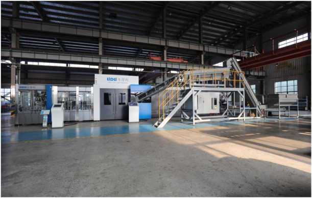
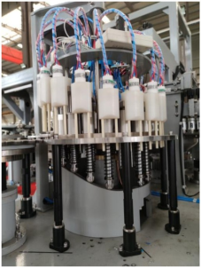
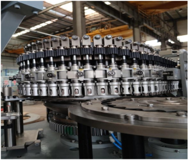
8. The appearance of the bottle blowing machine is as shown in the figure
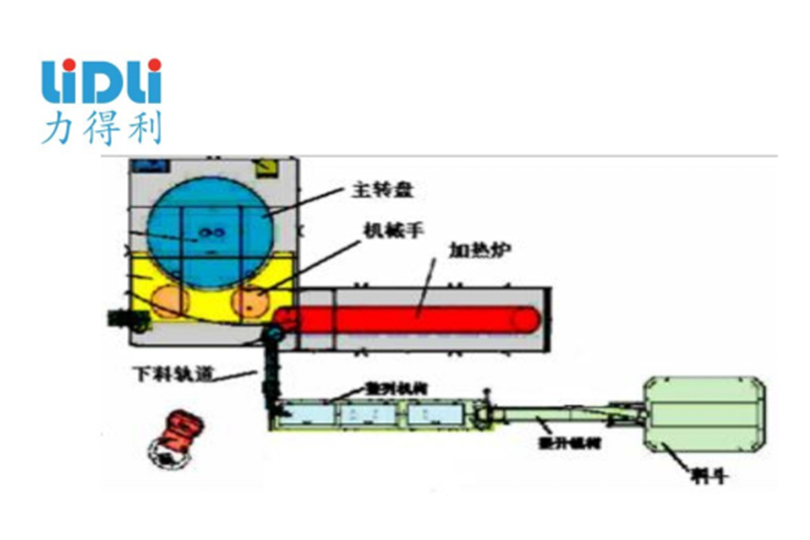
The fully automatic rotary bottle blowing machine is a high-speed two-part product independently developed by our company by absorbing the most advanced bottle-making technology in the world today
The step-by-step bottle blowing machine mainly consists of an automatic feeding and conveying device (hopper, lifting mechanism, alignment mechanism and discharging track) and heating
It consists of a furnace, a main blower, an electrical control system and a pneumatic control system.
The preforms are added to the hopper → the feeding conveyor belt lifts them to the alignment mechanism → The preforms are arranged in sequence → the discharging track
The process → bottle blowing machine heating furnace → The mechanical hand takes the heated preform out of the heating furnace and feeds it into the mold → The mold closes and locks
Start blowing the bottles immediately → The bottles are blown into shape → The bottle-taking mechanical hand takes them out → Exit the bottle mouth
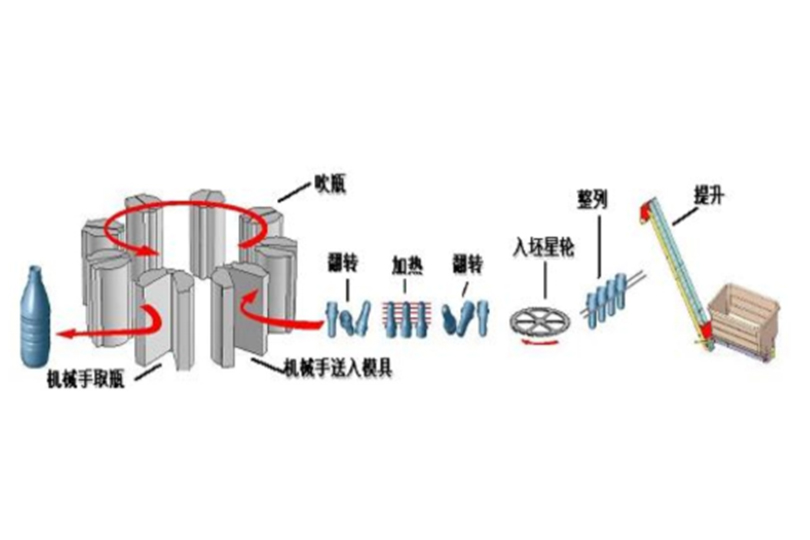
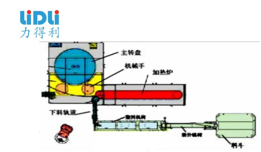
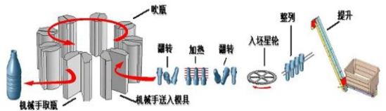 (Process Flow Chart)
9. Hopper and feeding mechanism
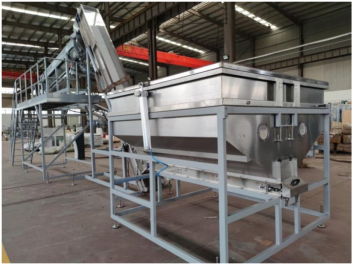 (Note: An automatic preform feeding system is adopted, with a top cover to effectively prevent dust from falling in. At the same time, a buffer-type preform hopper is used to prevent preforms from falling in the occurrence of bumps and bruises reduces the risk of leakage in the final product.)
Store a certain amount of preforms in the hopper to ensure the continuity of production. The conveyor belt in the hopper lifts the preforms to the preform sorting mechanism
The preforms are neatly arranged in a row and enter the heating furnace equipment of the bottle blowing machine along the discharging track.
Equipment performance description
The preforms are placed into the hopper and are immediately monitored by a computer. Without any assistance, the feeding volume of preforms can be automatically adjusted according to the production speed. The root
According to different types of preforms, the output speed can be adjusted arbitrarily to make the conveying volume of preforms match the production. Rotary plastic conveying
The belt and rotating roller conveyor ensure that the preforms are not damaged or contaminated during the transfer process.
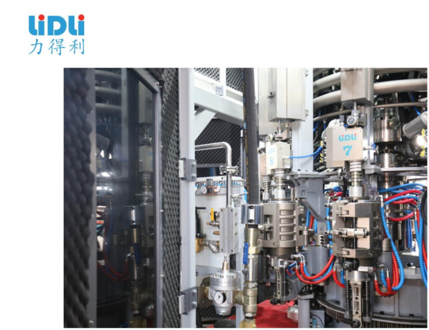
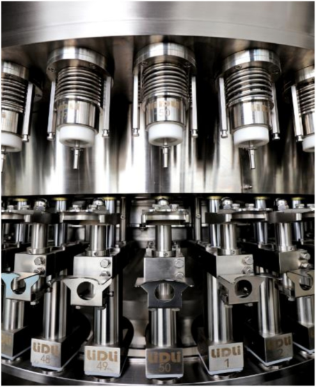
10. Heating furnace
 (Note: The heating furnace adopts a synchronous belt drive method, without the need to add lubricating oil, effectively avoiding the contamination of the preforms. At the same time, it uses the riveted furnace chain avoids the elongation phenomenon during the use of traditional furnace chains.)
For the preforms that have been arranged and entered the equipment, they are conveyed to each preform taking seat through the guide turntable. After the preforms are obtained by the preform taking seats,
They are sent into the heating furnace in sequence for heating. The heating furnace heats the preforms through infrared lamps, and each section of the infrared lamps
The temperature can be adjusted independently. The fan at the bottom of the heating furnace performs thermal circulation to ensure uniform temperature inside the furnace.
It adopts a large mold base, which has strong compatibility with bottle types and can switch between 200ml and 2000ml bottle types (mold data is calculated separately).
The specially designed mold base system ensures rapid and accurate mold replacement with good interchangeability. The mold base is equipped with a pressure balancing device.
This ensures that the clamping line of the bottle is minimized during the blow molding process, guaranteeing the quality and performance of the bottle. The special sealing design ensures the blank
The pressure when the mouth comes into contact with the sealing mouth is the least, and it will not damage the mouth of the preform.
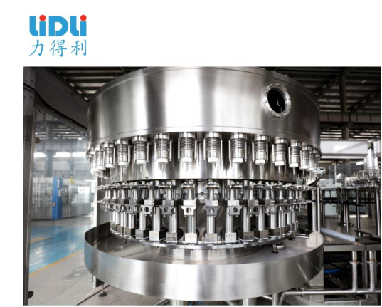
Filling section
After being blown by the bottle blowing system, the bottles are conveyed by the pulleys and enter the two-in-one filling machine. Through the bottle feeding pulley assembly, they are sorted into suitable bottles
The spacing is conveyed to the filling machine. The bottles entering the filling machine are held at the bottle mouth by the lifting cylinder and rise under the action of the lifting cylinder.
Overcome the effect of the filling valve spring to open the filling valve and start filling. After filling is completed, the bottle descends and leaves the bottle under the action of the CAM
Mouth. The filled bottles are conveyed into the capping machine by the transition wheel. A bottle mouth rinsing device is set at the transition wheel for the bottle mouth
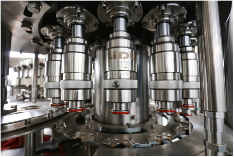
The possible residual materials at the threaded part are rinsed, and then enter the capping machine. The anti-rotation knife on the capping machine gets stuck at the bottleneck part and is maintained
Keep the bottle upright and prevent it from rotating. The capping head keeps orbiting and rotating on the capping machine. Under the action of the CAM, the capping head realizes the capping.
The capping, screwing and uncapping actions complete the entire sealing process. The finished bottles are conveyed from the capping machine to the bottle discharge conveyor by the bottle discharge wheel
On the chain, the three-in-one filling machine is conveyed out by the conveyor chain.
Transmission system
The motor adopts SEW motor with a power of 7.5kW.
The reducer is a SEW reducer: KAF87DRN132MC4, with a speed ratio of 49.16.
The gear module m =5
Main features of the equipment
The equipment has a compact structure, a complete control system, is easy to operate and has a high degree of automation. The main frame is welded with SUS304 stainless steel, solving the rusting problem of the frame in acidic environments
All parts in contact with materials are made of high-quality SUS304 stainless steel, with no dead corners in the process and easy to clean.
High-precision and high-speed filling valves are adopted, ensuring accurate liquid level without liquid loss and superior filling quality.
The bottle lifting in the filling section adopts a CAM lift, which is stable and reliable
The bottle rinsing and filling sections adopt large flat slewing bearings to ensure the smooth operation of the main machine
The cap head adopts a constant torque structure to ensure the quality of the cap.
The cap channel is equipped with a photoelectric detection system, which provides signals for cap blockage and cap shortage, and is linked with the main unit. At the same time, a bottle presence signal is set to ensure accuracy
Keep the cap on until there is no bottle left.
The equipment adopts the bottle feeding method of hanging the bottle mouth. Changing the bottle shape does not require adjusting the height of the equipment. It can be achieved simply by replacing the bottle-pulling star wheel
It's simple and convenient to do. The bottle discharge conveyor chain is synchronously controlled with the main machine to ensure the stability of bottle operation
The bottle discharge conveyor is set with a bottle blockage signal. When a bottle blockage occurs, the main unit is controlled to decelerate and shut down
The equipment is equipped with a fully automatic lubrication system, which can effectively lubricate the moving parts (bearings) of the equipment according to the system Settings.
It is equipped with complete protective devices, which can effectively safeguard the safety of the machine and the operator.
The control system is equipped with functions such as automatic control of the liquid level in the material cylinder, detection of missing caps, automatic stop of bottle rinsing, and counting of production volume.
The bottle washing system adopts high-efficiency cleaning spray nozzles produced by the technology of the American Spray Company, which can effectively clean the inner walls of containers.
The whole machine operation adopts advanced touch screen control, which can realize human-machine dialogue.
The control system can display production speed, shift output count, fault category, fault occurrence point, etc. on the screen.
It can also automatically calculate the time of fault occurrence, fault category and other information.
Lid-lifting and lid-arranging integrated machine
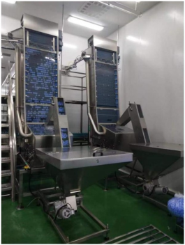
1. Equipment Overview
The TGLG type cap lifting and aligning machine utilizes the principle of the center of gravity of the caps to effectively remove reverse caps. The front caps are smoothly lifted to the predetermined height and enter the lower cap trough, where they are then conveyed to the cap aligning device. The reverse covers fall back into the cover hopper, while a few front covers that do not enter the lower cover trough are squeezed into the cover recovery cylinder and fall into the cover hopper. Repeat this cycle until all the LIDS are neatly arranged and enter the lower lid slot. This equipment adopts mesh chain conveying, featuring low noise, stable and reliable transmission. The Angle between the fuselage and the underframe is adjusted through the support shaft assembly. The adjustable Angle is between 75 and 85 degrees, and it can be adjusted to the best position according to the on-site conditions. This equipment is equipped with both manual and automatic functions. The production process of this machine is as follows
Manual mode: The lid-lifting and lid-arranging machine is started by manual point operation control to extract the lid. This mode is basically used for trial operation work.
Automatic mode: In automatic mode, the lifting motor starts and stops according to the program control requirements, achieving the process of lifting and arranging the covers, and completing the production
Production line cover supply requirements.
2. Main features
1) Lifting device
This section provides power for the entire cap-lifting and cap-arranging machine. The motor drives the active shaft, which is then transmitted to the mesh chain through the sprocket for linear movement Move to lift the lid. It is equipped with a tensioning device for adjusting the tightness of the mesh chain. The imported net chain meets the food hygiene requirements.
2) Cover bucket assembly
This section is used to store the LIDS. Pour the disordered LIDS into the lid hopper and wait for the lid support beam to be lifted. The cover bucket is equipped with a pressure relief device The board enables the bottle caps to enter the cap support beam in an orderly manner.
3) Blowing cover baffle device
The function of this part is to guide and regulate the lid being blown into the lower lid slot and sent to the lid aligner. It is equipped with an acrylic panel for easy adjustment Adjust the Angle of the air outlet.
4) Cover recovery device
This section effectively resolves the issue that some individual covers might not have been blown to the lower cover slot. Force the bottle cap back to the cap hopper, the same It prevents the equipment from jamming and plays a protective role.
5) The side panels of the equipment are made of SUS304 stainless steel plates, with a polished surface, presenting an overall elegant and stylish appearance.