Part I: Preparation 1.1 Prepare all tools that may be used during the construction process 1.2 Clean the upstream water inlet pipeline; 1.3 Carefully evaluate the quality of the water inlet; 1.4 Check whether the pipeline has leaks; 1.5 Prepare water-soluble lubricants (chemically pure glycerin); 1.6 Ensure that all parts and chemicals used are complete; 1.7 Check the operation of the pretreatment system and the normal water output.
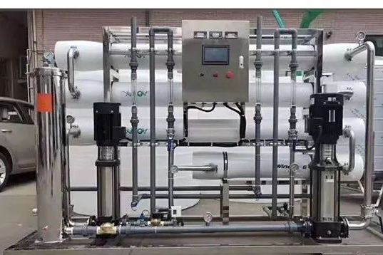
Part II: Dismantling the old reverse osmosis membrane and installing the new membrane 2.1 Dismantle the pressure vessel of the reverse osmosis membrane, unify all the end covers and parts, and store them in order. 2.2 Take out the old reverse osmosis membrane element in the pressure vessel and rinse the pressure vessel. 2.3 Take out the new membrane element and check whether the position and direction of the brine sealing ring on the element are correct (the opening direction of the brine sealing ring must face the water inlet direction). 2.4 Push the end of the membrane element without the brine sealing ring into the membrane shell parallel to the water inlet end of the pressure vessel until the element is exposed about 10 cm outside the water inlet end of the pressure vessel. 2.5 Insert the connecting pipe between the elements into the central tube. Before installation, apply a small amount of glycerin lubricant on the "O" ring of the joint. If not, you can also directly wet it with qualified pre-treated water. 2.6 Take out the second membrane element, check whether the position and direction of the brine sealing ring on the element are correct, hold the element and insert the connecting pipe on the first element into the central tube of the element, and push the element into the pressure vessel in parallel until the second element is about 10 cm exposed outside. 2.7. Repeat the steps until all elements are installed in the pressure vessel, transfer to the concentrated water end, and install the connecting pipe on the central tube of the first element. The length of the element and the pressure vessel determines the number of membrane elements that can be installed in a single pressure vessel. During installation, install a thrust ring at the concentrated water end of the pressure vessel. 2.8. Check the "O" ring on the element adapter, insert the element adapter into the concentrated water end plate, align the element connection pipe and push the concentrated water end plate assembly into the pressure vessel in parallel; rotate and adjust the concentrated water end plate assembly to align it with the external connection pipe; install the end plate clamping ring 2.9 Push the membrane element from the water inlet side to the concentrated water side until the first installed membrane element is firmly in contact with the concentrated water end plate. 2.10. Install the water inlet end plate. Before installing the water inlet end plate, in order to prevent the axial movement of the element and the impact between the elements when the system is started and stopped, the gap between the membrane element and the end plate can be adjusted with an adjustment sheet (thickness 5mm). 2.11 Repeat the above steps, install the membrane element in each pressure vessel and connect all external water inlet, concentrated water and production water pipelines.
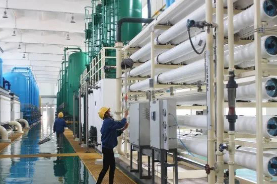
Part III: Equipment commissioning 3.1 Inspection and preparation before commissioning, including the following parts: 1. Configure measuring instruments and calibrate each instrument; 2. Set sampling points in each link of the system, and correctly set interlocking, delay and alarm devices; 3. Check the connection of pressure vessels and cleaning pipelines, and tighten all joints; 4. No-load test run of rotating equipment such as water pumps to ensure correct steering and good lubrication; 5. Open the water production discharge valve and the concentrated water discharge valve; 6. Before starting the high-pressure pump, adjust the opening of the high-pressure pump outlet valve to control the membrane system water flow rate to be less than 50% of the operating water flow rate. 3.2 Check all valves and ensure that all settings are correct. The membrane system water production discharge valve, water inlet control valve and concentrated water control valve must be fully opened. 3.3. Use low-pressure, low-flow qualified pre-treated water to drive away the air in the membrane element and the pressure vessel. All water production and concentrated water in the process should be discharged to the sewer.
3.4. During the flushing operation, check whether there are leaks at all valves and pipe connections. 3.5 For dry membrane systems, low-pressure flushing should be performed continuously for more than 6 hours or flushed for 1 to 2 hours first, soaked overnight and then flushed for about 1 hour. During low-pressure and low-flow flushing, it is not allowed to add scale inhibitors to the pretreatment part. 3.6. Confirm again that the water production valve and the concentrated water control valve are in the open position. 3.7 When starting the high-pressure pump for the first time, the water inlet control valve between the high-pressure pump and the membrane element must be in a state close to full closure to prevent the impact of water flow and water pressure on the membrane element. 3.8 Start the high-pressure pump. 3.9 To avoid over-flow and over-pressure impact on the membrane system, the high-pressure pump outlet water inlet control valve should be slowly opened after the high-pressure pump is started to evenly increase the concentrated water flow to the design value, and the pressure increase rate should be less than 0.07 MPa per second. 3.10. While slowly opening the high-pressure pump outlet water inlet control valve, slowly close the concentrate control valve to maintain the concentrate discharge flow specified in the system design, while observing the system water flow, and gradually adjust the recovery rate to the design value. 3.11 Check whether the dosage of all chemical agents is consistent with the design value, and measure the pH value of the inlet water. 3.12. The system runs continuously for 1 hour. When the water production is qualified, first open the qualified water production delivery valve and then close the water production discharge valve to supply water to the subsequent equipment. Record all operating parameters of the first group. The above adjustments are generally carried out in manual operation mode, and the system is converted to automatic operation mode after stabilization. 3.13 After 24 to 48 hours of continuous operation, check all recorded system performance data, including inlet pressure, pressure difference, temperature, flow, recovery rate and conductivity. At the same time, sample and analyze the inlet water, concentrate and total system water production. Confirm that the equipment is operating normally and the construction is completed.


 2026